 Here at Riak we recently open source Riak TS, a new time series database built on the same foundation as Riak KV. Riak TS was selected by Intellicore to be the storage engine behind their sports platform currently being used by Formula-E to drive their second-screen experiences and mobile apps with final race days held in London on July 2nd and 3rd. So, it seemed fitting to build an “attraction” with some form of motor racing/Riak TS themed to show at the Riak stand at Strata London. I volunteered to do “something” with an old micro-Scalextric set and one of my Raspberry Pis. “Something” turned out to be a “who can get the fastest lap-time” game. The photo shows the setup.
Hardware
The kit list for the attraction was:
- A micro-Scalextric set. Micro-Scalextric is 1:64th scale as opposed to “normal” Scalextric which is 1:32nd scale. The set I bought some years ago (for family fun despite having two children who showed no interest in slot car racing, electrics or any other such thing – a great disappointment!) was the one with two Aston Martin DBS cars. One red car and, one green car. The colour becomes important later, well at least to certain of my colleagues.
- A Raspberry Pi. In keeping with our other stand attraction (a cluster of 6 Raspberry Pis running a five node Riak cluster and a display node), I decided to use an old Raspberry Pi Model B (rev 1) that I had. It is the oldest and most under-gunned of the Pis I own but that did not stop it from working perfectly in the role to which it was assigned.
- A limit switch. More about this later!
- A TP-Link 5 port Ethernet Switch for internal networking, an absolute bargain at £6 from PC World!
- My MacBook Pro running a Linux Mint VM inside VirtualBox, which is the platform for a single node of Riak TS 1.3 with which I have built a number of Riak TS demonstrations.
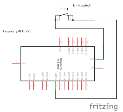
The following circuit schematic shows the connecting of my Raspberry Pi and the limit switch. The circuit was very simple indeed as can be seen. (The schematic was created in the open source package “Fritzing”).
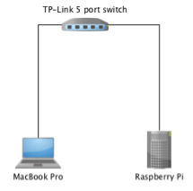
To interface the Pi to Riak TS, running on the guest virtual machine on my MacBook, I created a simple LAN via the TP-Link ethernet switch as so:
The limit switch was mounted on a bracket made from two pieces of Meccano (yes this whole exercise was an excuse for a massive nostalgia trip for me….) mounted on Blu Tack next to the side of the track where it could be engaged by a car whipping around the track.
Detecting cars – or a tale of three switches
Initially I thought that I would use a magnetic reed switch to detect the passing of a car to trigger lap timing, etc. I duly bought the entire stock (two!) of such switches from my local electronic components store andrigged a test circuit on breadboard and set about detecting events. The switch happily triggered when a small stack of neodymium magnets I had lying around (don’t ask!) was passed to and fro in front of it. My Scalextric cars have two small such magnets on the chassis to help the cars stick to the track while racing. These were not enough to trigger the switch so I use tape to attach a few more on the side of the car. By time I had enough to trigger the switch, the car was undrivable. Back to the drawing board.
I next decided to use optical sensing. I found a fascinating video on YouTube about making a homemade photogate. So off to my local store again. I drew a number of blank looks when asking for a matched pair of an InfraRed LED and a phototransistor. Eventually, someone grunted and provided a kit from which I could scrounge such a matched pair. So off back home to complete the photogate. All the connections checked out after I had soldered them. I connected the photogate to the breadboard, made the other needed connections and set about testing. Absolutely nothing. Back to the drawing board.
In desperation I opted for a mechanical limit switch, despite that being “old, “boring” technology. I mean we were using limit switches back in the ‘eighties when I studied Engineering at University! However, old and boring worked perfectly every time.
Software and how it all came together
My Raspberry Pi was loaded with the latest version of Raspberian, the Debian based OS. I uninstalled a number of programmes, such as LibreOffice, because I did not want them and in my opinion using a Pi for office work is naff, and I wanted to reclaim the “hard disk” space on the SD card!
The limit switch was wired between a +3.3V pin on the Pi and GPIO04, a free input pin. (Remember Pi input pins only work with 3.3V – don’t blow your Pi by connecting a GPIO pin to +5V). After some experimentation, GPIO04 was set with a pull down resistor in software to ensure that it read 0V normally as due to “interference” from the power input of the Pi (which was connected by USB to the MacBook where I was running Riak TS) the signal level at the pin, and hence whether an event was detected or not, wobbled alarmingly. Another characteristic of switches is they “bounce” – when they are opened or closed the contacts wobble causing what looks like a bounce on an oscilloscope. The more expensive the switch, the better made it is and the less bounce it exhibits. The switch I had courtesy of that local store was cheap but it did the job. Luckily, the standard software library GPIO for physical computing on the Raspberian platform with Python has a setting to overcome switch bounce in software, of which I made full use.
I wrote a Python programme for the Pi as per the following flowchart:
The actual code as used is on the github repository for this project: https://github.com/datalemming/strata-cars.git
For clarity, the prime script for data acquisition and storage was “race.py” (I believe in simple names…..)
This is as follows:
The first section loads the necessary Python libraries and initialises the RPi to Broadcom mode (the default). It sets up (logical) Pin 4 as the input pin and initialises some variables to keep laptimes and whether the lap is the first for that driver or not. It also captures the drivers email address, which is used as an identifier.
import time
from datetime import datetime
from riak import RiakClient as rc
import RPi.GPIO as GPIO

GPIO.setmode(GPIO.BCM)

channel=4
GPIO.setup(4, GPIO.IN,pull_up_down=GPIO.PUD_DOWN)

start=time.time()
stop=time.time()
firstlap=True
driveremail=str(input("Enter driver's email to start\n"))
print "Driver you may start your laps\n"
laptimes=[]
This next section is the procedure to add the lap times to Riak TS. It is called when the <CTRL>+<C> keyboard combination is detected, which happens when the driver has done enough laps or has crashed (which was usually the case!).
##
def addLapTimes(laptimes):
lts=laptimes
print lts
host='192.168.0.15'
port=8087
nodes=[{'host':host,'port':port}]
conn=rc(protocol='pbc',nodes=nodes)
print conn.ping() #should be True
t=conn.table('stratalaptimes')
print t
#set time stamp
records=[]
timestamp=int(time.time()*1000)
print timestamp

#iterate through the laptimes list
for l in lts:
print l
r=["StrataLondon",timestamp,l[0],l[1]]
print r
records.append(r)
timestamp = timestamp+1000
to=t.new(records)
print "Created table object"
print "Store result: ",to.store()
This section is the callback procedure that is run every time a given event is detected on the input pin 4. The procedure gets the start time and end time of laps and calculates the lap time (end-start). Lap times are added to the list structure “laptimes”.
##
def my_callback(channel):
global start, stop, firstlap, driveremail,laptimes
if (firstlap==True):
start=time.time()
firstlap=False
print "Lap timing started"
else:
result=[]
stop=time.time()
laptime=stop-start
start=stop
result.append(driveremail)
result.append(laptime)
print driveremail," Laptime= ",laptime," s"
laptimes.append(result)
This final section of the script adds a detection event for a ‘rising edge” on Pin 4. That means as the car passes the switch and engages it a pulse of voltage will be detected on Pin 4. I opted to use the detection of the rising edge of that pulse to trigger the timing procedure as it would give the best lap times. Also, on the end of a run, the user hits the <CTRL>+<C> key combination and that triggers the writing of the results to the Riak TS table and cleans up and ends execution.
GPIO.add_event_detect(channel, GPIO.RISING, callback=my_callback, bouncetime=200)

try:
 while True:
 time.sleep(0.1)
except KeyboardInterrupt:
 GPIO.cleanup()
 print laptimes
 #now to input lap times into Riak
 addLapTimes(laptimes)
During the event, the Pi was accessed via SSH from my MacBook, so everything could be kept self contained.
On the MacBook I ran a number of windows in the VirtualBox Linux Mint guest, one showing the riak-shell (a SQL repl for ad hoc querying etc. of Riak TS), with which I ran a query after every run to show users that their lap data had been saved and one showing a Jupyter notebook, with which I wrote some Python code to show a leaderboard etc.
On the day
The attraction worked perfectly – I’d like to say that was testament to my engineering abilities, but I expect it was blind luck. The fastest lap time recorded was 0.928 seconds – an amazing performance. I spent most of my time repairing the cars however, which had an alarming tendency to come off the track and go flying at around the 1.1 second lap time.
As regards cars and their colours, amongst my colleagues, it was widely believed that the green car was the fastest. Unfortunately, I did not record the colour of the car that a user used, otherwise I could agree or otherwise with that statement through analysis of the data (which after all is the name of the game!). I would point out, that as the green car was the one used most, it was also the one repaired most times. I am surprised it was still going at the end of the event!


